If you’re the sort of person who has to check the stove is off before leaving the house, then recheck it because you can’t remember if you checked it (and maybe even turn around at the front gate, unlock the door, go back inside and check a final time) – this might be the project for you.
Before I get into it, if you haven’t already, check out the other projects I’ve built for LinuxScrew:
- Python Powered Tank!
- Python Powered Tank Part II
- Python Powered Tank Part III – The Finale
- Smart Mirror
- Wikipedia Scraper
- Photo Resizer and watermarker
- Raspberry Pi Powered Palmtop/Laptop
- Raspberry-Pi augmented Apple Macintosh
- Arduino Controlled Soldering Extraction Fan
What is it?
The purpose of this box is to let you know you’ve done everything you need to do before leaving the house.
As you complete each task, flick the associated switch, and the LED beneath it will be illuminated. When they’re all illuminated, they’ll stay on – letting you know you’re ready to go.
After 5 minutes, the box will reset itself, turning off the LEDs ready for the next day.
This project illustrates how a simple circuit and some basic Arduino coding can be used to make a useful tool for around the house – it should make for a good Saturday afternoon project, especially if you’re learning how to build things and want to make something simple but useful to get started.
The Parts
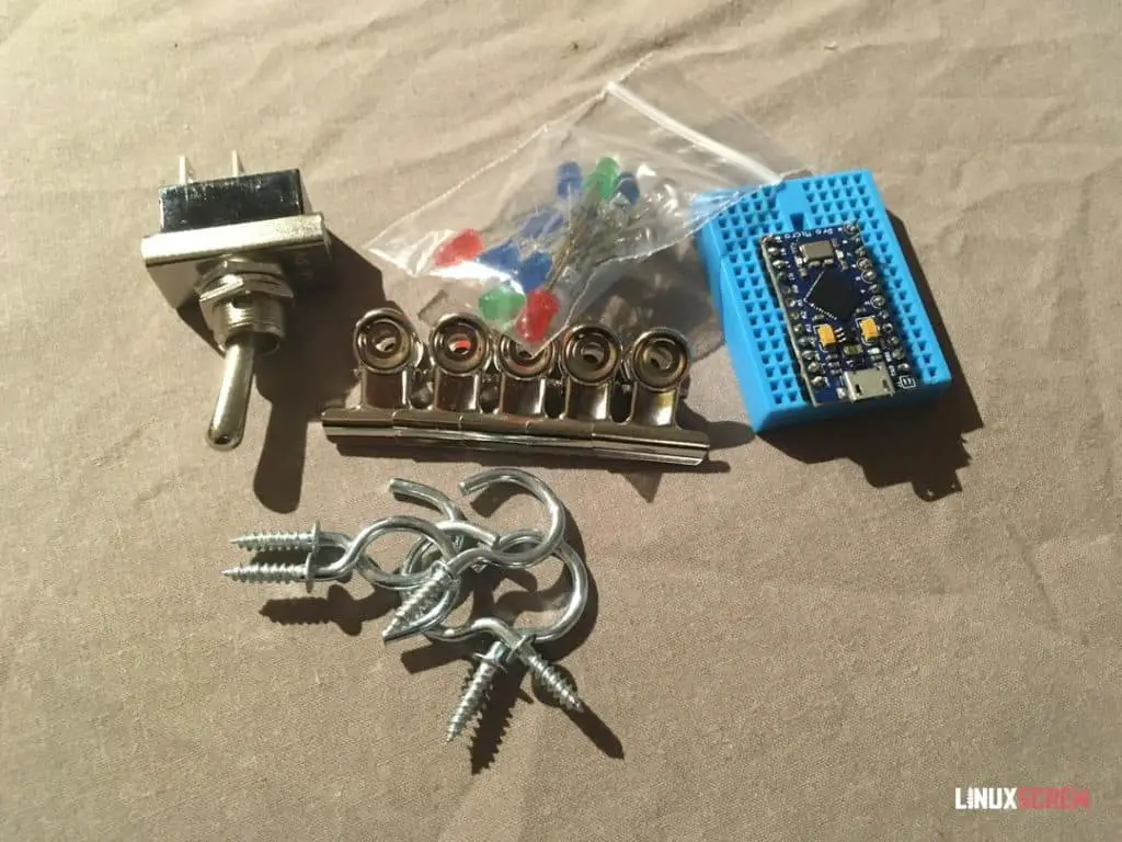
Here’s a list of the parts involved – total cost less than about $20.
- Arduino
- Bread/prototyping board
- Momentary toggle switches (or any momentary switch, push-button, etc.)
- LEDs
- 100 Ohm resistors
- A box
- Assorted lengths of wire
- Assorted glue/tape
- Hooks/bulldog clips
The “Arduino” I’m using is a generic brand knock-off that identifies as an Arduino Leonardo – it is called a “Pro Micro” – found online for a few dollars each.
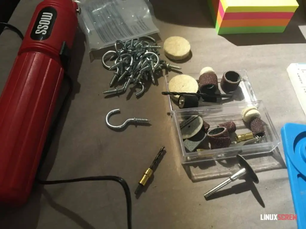
I’ll use the following tools:
- Soldering Iron
- Dremel/cutting tool
- Pencils/ruler
- Arduino IDE to write the code and load it onto the Arduino board

I’ve upgraded my workspace from the kitchen to a better workbench with a work mat and some extra tools – but I’m still avoiding things like 3D printers and laser cutters to keep these projects accessible. This project uses the world’s cheapest Dremel clone, which was about $20 – and it actually did the job pretty tidily, to my surprise.
The Build
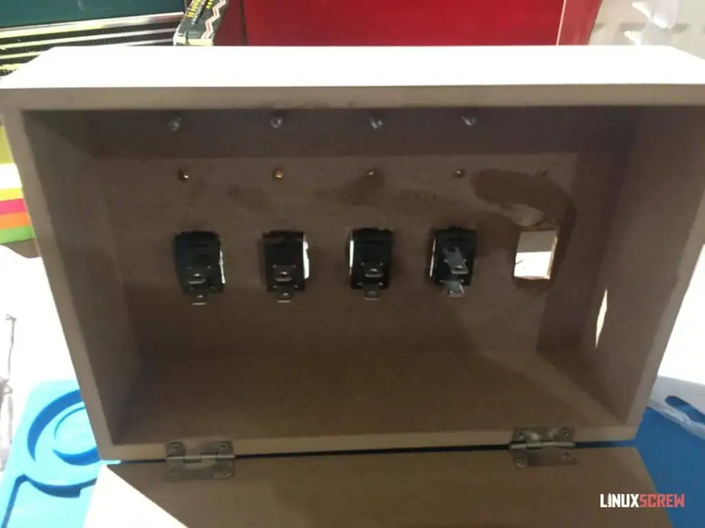
First, I’ve cut away at the box to make holes for the switches, LEDs, and hooks.
The LEDs will poke through the drilled holes so you can see them from the outside.
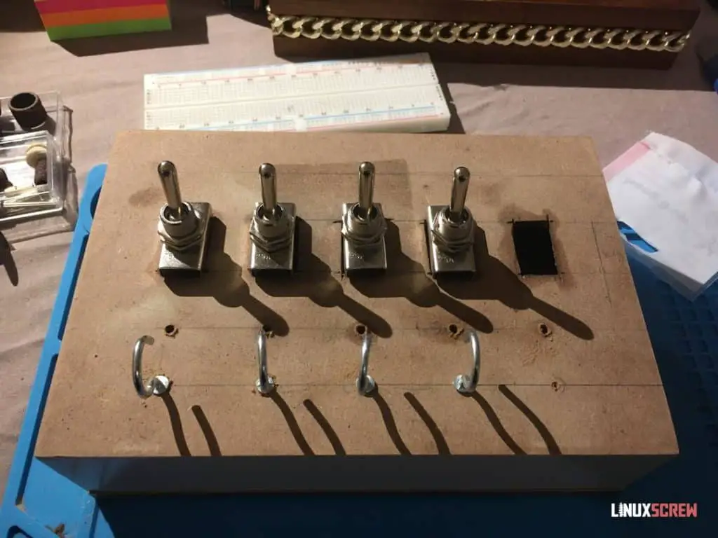
Hooks are added so that tasks/things to remember can be easily added and removed.
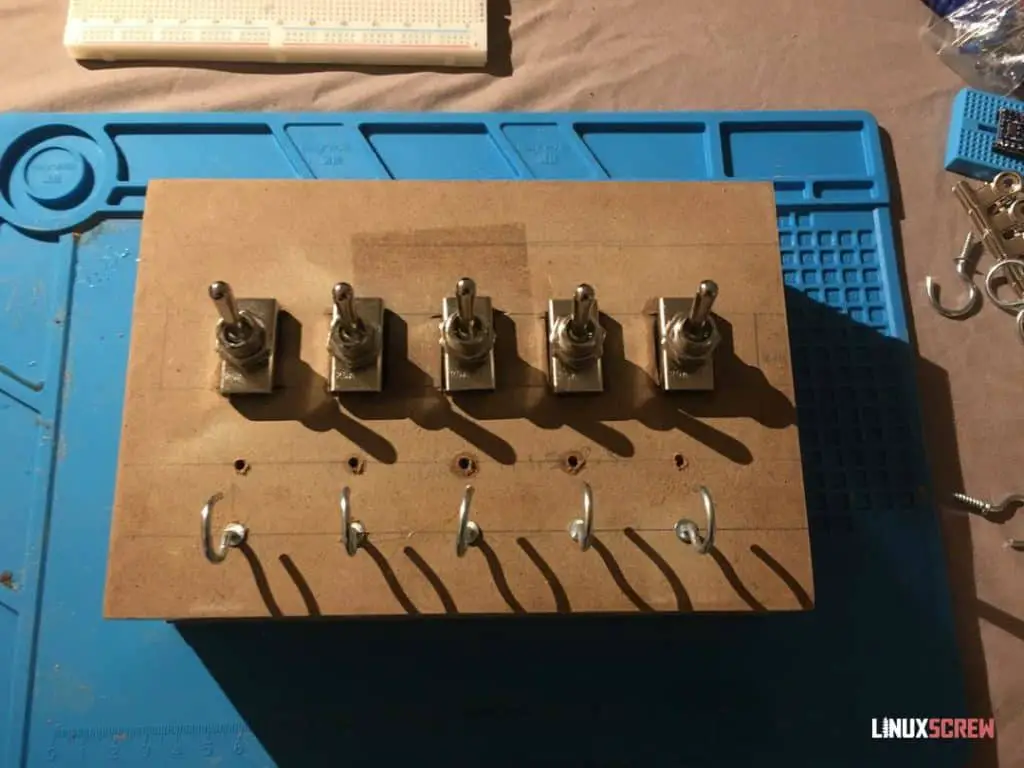
Everything fits! This is actually coming together pretty well.
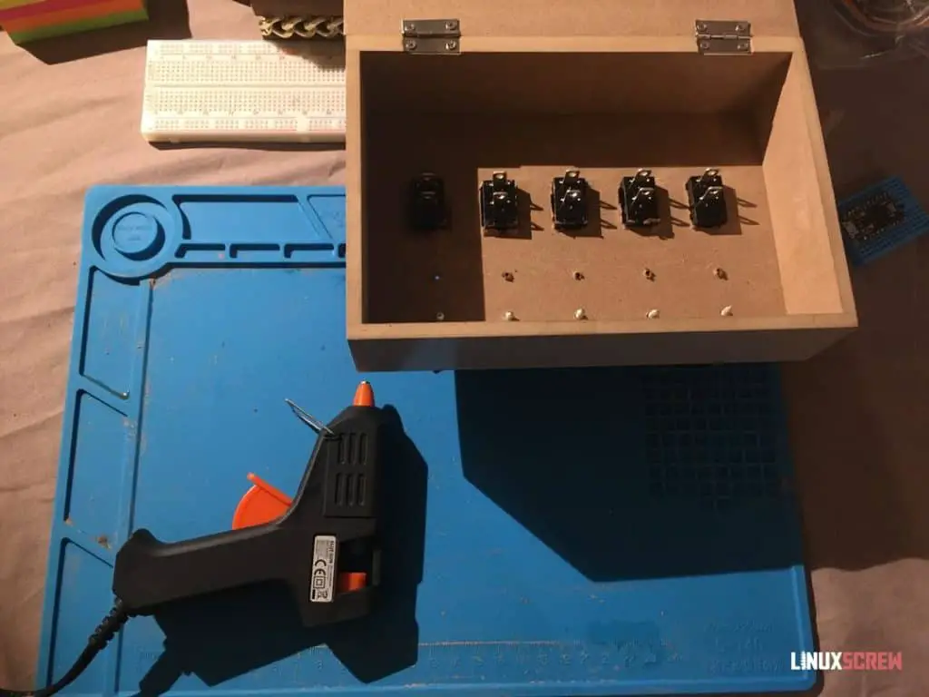
The inevitable appearance of a hot glue gun – used to reinforce the switches. They make a satisfying ‘thunk’ when flicked, but it takes a bit for force, so I don’t want them coming loose.
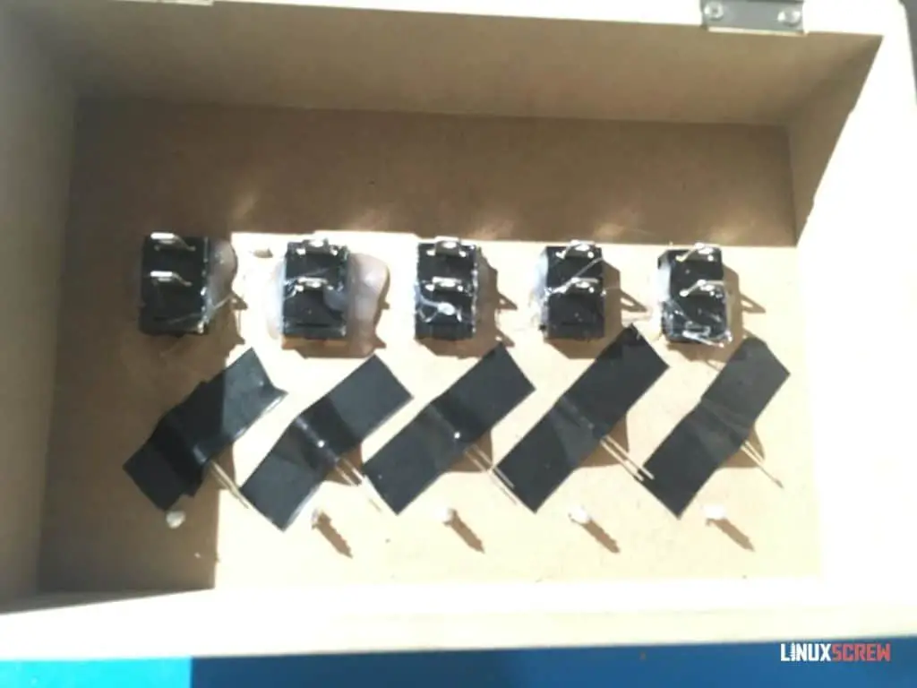
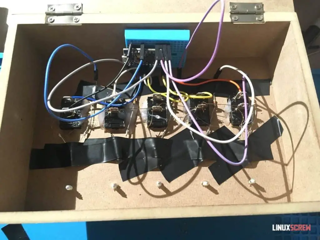
The LEDs are taped behind each drilled hole so they can shine through when lit up.
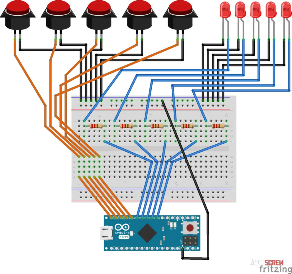
And here’s the standard messy wiring job – each switch and LED is wired to one of the Arduino digital pins.
All LEDs, switches, and the Arduino have their ground pins wired together – this is important! Everything must share a common ground.
The short pin on LEDs should always be connected to ground – they are not reversible.
A 100 Ohm resistor is placed between each LED and the Arduino – otherwise, they will suck up as much current as possible, burning out quickly (and robbing other components of power).
See the circuit diagram below for what’s going on:
This could probably be achieved with a more complicated electronic circuit and no code/micro-controller, but that’s the great thing with the Arduino platform – it can replace a bunch of other hardware (and the know-how on how to use that hardware) with a single board and some simple code.
The Code
The code is pretty simple – basic reading of the switch states, turning on and off LEDs, and some If statements to perform actions conditionally. The code is commented so you can see what’s doing what.
// This is the code for the DIY Arduino Powered Morning Reminder/Checklist Gadget... Thing
// Project build details at LinuxScrew.com

// Variables defining which arduino pins are attached to the momentary buttons/switches (henceforth just referred to as the switches)
int switch1Pin = 2;
int switch2Pin = 3;
int switch3Pin = 4;
int switch4Pin = 5;
int switch5Pin = 6;

// Variables defining which arduino pins are attached to LEDs
int led1Pin = 7;
int led2Pin = 8;
int led3Pin = 9;
int led4Pin = 10;
int led5Pin = 16;

// Variables to store the current state of the switches in the loop
// There are two states - HIGH and LOW voltage levels, low being when the pin is grounded
// The Arduino will be able to read whether a pin is HIGH or LOW and we can use that to determine whether the switch was pressed
// They will be defaulted to HIGH, so that when the switch is pressed, it is grounded and will read LOW
int switch1State = HIGH;
int switch2State = HIGH;
int switch3State = HIGH;
int switch4State = HIGH;
int switch5State = HIGH;

// Variables to store whether the switches have been pulled since the last reset in the loop
// The switches are only active momentarily, so we need variables to remember if they have been previously pressed
bool switch1Pulled = 0;
bool switch2Pulled = 0;
bool switch3Pulled = 0;
bool switch4Pulled = 0;
bool switch5Pulled = 0;

// Time to delay before resetting the system after all switches pulled
long delayTime = 300000; //ms, 5 minutes

void setup() {
    // The setup() function is run once when the Arduino is finished booting
    // It's used to set up the system

    // Set the switch pins to INPUT mode - as we will be reading their state
    pinMode(switch1Pin, INPUT);
    pinMode(switch2Pin, INPUT);
    pinMode(switch3Pin, INPUT);
    pinMode(switch4Pin, INPUT);
    pinMode(switch5Pin, INPUT);

    // Set the LED pins to OUTPUT mode, as we will be changing their output to turn the LEDs on and off
    pinMode(led1Pin, OUTPUT);
    pinMode(led2Pin, OUTPUT);
    pinMode(led3Pin, OUTPUT);
    pinMode(led4Pin, OUTPUT);
    pinMode(led5Pin, OUTPUT);

    // Set the LED pins to LOW - turning them off to start with
    digitalWrite(led1Pin, LOW);
    digitalWrite(led2Pin, LOW);
    digitalWrite(led3Pin, LOW);
    digitalWrite(led4Pin, LOW);
    digitalWrite(led5Pin, LOW);

    // Set the switch pins to HIGH - this way, when they are pressed, they will read LOW (as they've been grounded) and we can use that to check if they have been pressed
    digitalWrite(switch1Pin, HIGH);
    digitalWrite(switch2Pin, HIGH);
    digitalWrite(switch3Pin, HIGH);
    digitalWrite(switch4Pin, HIGH);
    digitalWrite(switch5Pin, HIGH);

    // Enable serial output so we can see what the Arduino is doing from the Arduino IDE serial console - good for debugging
    Serial.begin(9600);
    Serial.println(F("Toggle-switch todo thing ready to go."));

    // Wait a second for everything to get ready before continuing
    delay(1000);// ms

}

void loop() {
    // The code in the loop() function will run repeatedly every few moments - it's where the main logic for this gadget goes.
    // When it's finished executing, it executes again, non stop.

    // Read the state of each button right now
    switch1State = digitalRead(switch1Pin);
    switch2State = digitalRead(switch2Pin);
    switch3State = digitalRead(switch3Pin);
    switch4State = digitalRead(switch4Pin);
    switch5State = digitalRead(switch5Pin);

    // If a button is being pressed, it will read LOW
    // If a button is pressed, output a message to the serial console so we can see it while testing
    // Then, the variable tracking whether the switch has been pressed is updated, and the respective LED is illuminated by setting it to HIGH
    if (switch1State == LOW) {
        Serial.println(F("Switch 1 flicked."));
        switch1Pulled = 1;
        digitalWrite(led1Pin, HIGH);
    }

    // This is then done for all switches/LEDs
    if (switch2State == LOW) {
        Serial.println(F("Switch 2 flicked."));
        switch2Pulled = 1;
        digitalWrite(led2Pin, HIGH);
    }

    if (switch3State == LOW) {
        Serial.println(F("Switch 3 flicked."));
        switch3Pulled = 1;
        digitalWrite(led3Pin, HIGH);
    }

    if (switch4State == LOW) {
        Serial.println(F("Switch 4 flicked."));
        switch4Pulled = 1;
        digitalWrite(led4Pin, HIGH);
    }

    if (switch5State == LOW) {
        Serial.println(F("Switch 5 flicked."));
        switch5Pulled = 1;
        digitalWrite(led5Pin, HIGH);
    }

    // If all switches have been pressed, wait 5 minutes and then reset the system by turning off all of the LEDs and reseting the pulled variable for each switch
    if (switch1Pulled == 1 && switch2Pulled == 1 && switch3Pulled == 1 && switch4Pulled == 1 && switch5Pulled == 1) {
        Serial.println(F("All switches flicked."));

        delay(delayTime);

        digitalWrite(led1Pin, LOW);
        digitalWrite(led2Pin, LOW);
        digitalWrite(led3Pin, LOW);
        digitalWrite(led4Pin, LOW);
        digitalWrite(led5Pin, LOW);

        switch1Pulled = 0;
        switch2Pulled = 0;
        switch3Pulled = 0;
        switch4Pulled = 0;
        switch5Pulled = 0;

    }

}

// End of code!
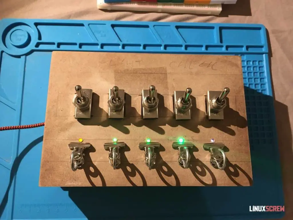
The code works! I’ll tidy up the appearance and put it to use.
The Finished Product
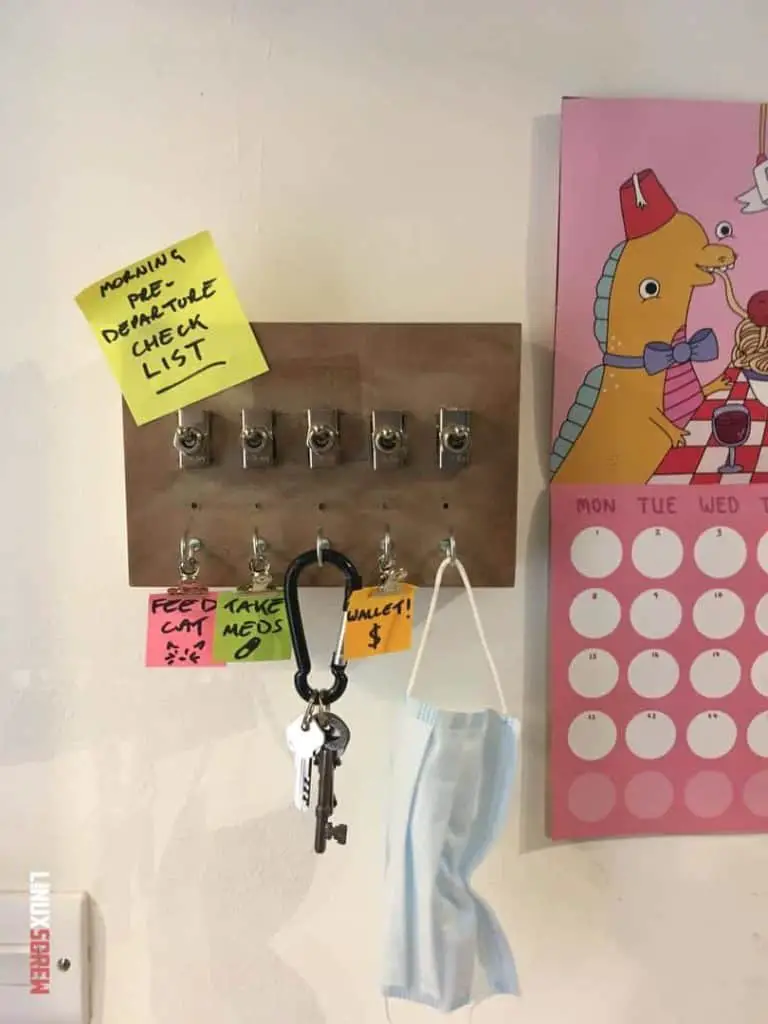
This has actually turned out pretty well. It’s got an old switchboard/circuit breaker aesthetic – I’m pretty happy with it.
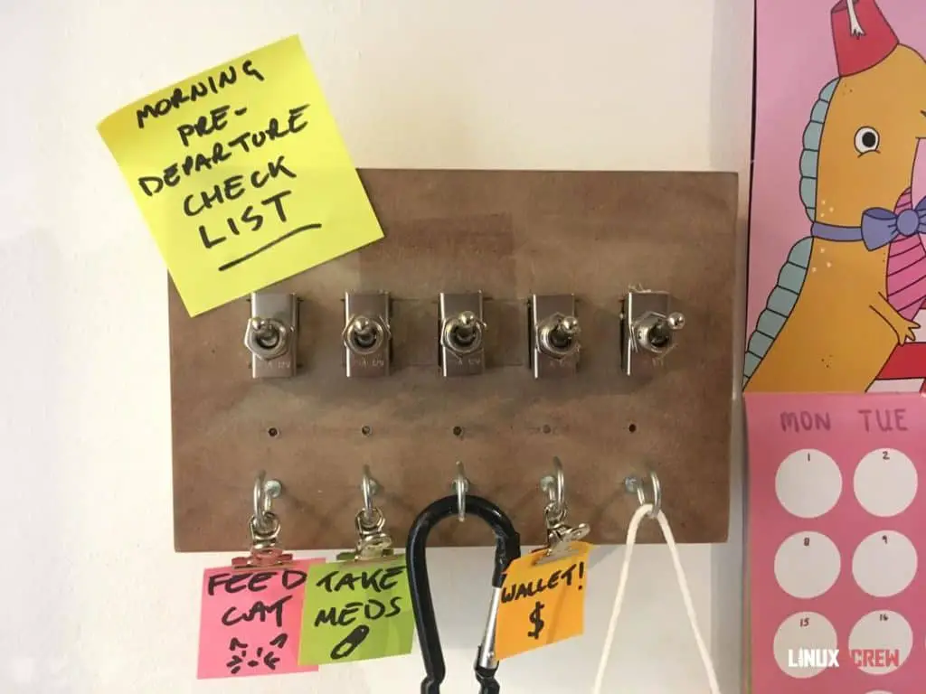
Of course, I have several improvements I’d like to make in a future revision:
- A buzzer to buzz when all tasks are complete – an audio queue that, yes, you can leave the house, you haven’t forgotten anything.
- Maybe a built-in night light on a timer with a button on the side for coming home late in the dark.
- Running a USB cable to the Arduino for power is a bit of an eyesore – I wonder if solar panels on the top would provide enough power to keep a battery charged for running it.
Build Video
I’ve started putting together some short videos of the build process for these projects because why not. Check it out below:
And that was the Arduino Powered Morning Reminder/Checklist Gadget… Thing.
If you want to see more of this stuff, follow LinuxScrew and myself on Twitter.


