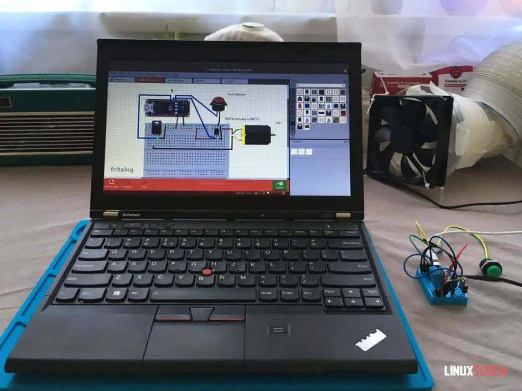
This article will show you to build a DIY soldering extraction fan (to ventilate fumes) using an Arduino and a temperature sensor to activate the fan when the soldering iron is hot.
Before you read this, why not open up my other projects in some new tabs for further reading when you’re done?
- Smart Mirror
- Wikipedia Scraper
- Photo Resizer and watermarker
- Raspberry Pi Powered Palmtop/Laptop
- Raspberry-Pi augmented Apple Macintosh
- Python Powered Tank!
The Project
A thoughtful commenter on a previous article suggested I get an extraction fan to use while I solder.
Bringing to attention the fact that:
- I suck at soldering and burn more solder than is probably safe
- I don’t have a proper work area
They were probably unaware of the fact that:
- I’m too lazy and/or forgetful to actually turn on any extraction fan that’s present.
- I didn’t inhale
Anyway, a technical solution is in order. After setting up a new work area with a soldering mat, I got to work on building an automatic extraction fan.
The aim is to have a fan that will switch itself on when I start soldering by reading a temperature change.
The Parts
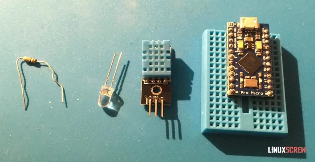
- 10mm Plastic tube
- 10mm 5v USB powered fan
- 5v USB bus-powered fan because I want to power it from the Arduino if possible
- A standard 12v PC fan wouldn’t suit unless I added a 12v power supply
- Arduino (mine’s some kind of clone, but it says ‘Pro Micro’ on it and identifies itself as an Arduino Leonardo)
- As you can see, this Arduino has seen better days – it’s been wrenched off of various things and re-used, but it still works
- DHT11 Sensor – it senses temperature and humidity, and it’s cheap
- MOSFET – this allows you to turn the power to the fan on/off from an Arduino pin – it’s basically a switch you can toggle by changing the voltage on the control pin
- Resistor
- I had originally planned to use an LED but instead replaced it with a push button to allow for manually turning the fan on
- There was limited room on the breadboard I was using to have both, and the Arduino has an LED on it anyway.
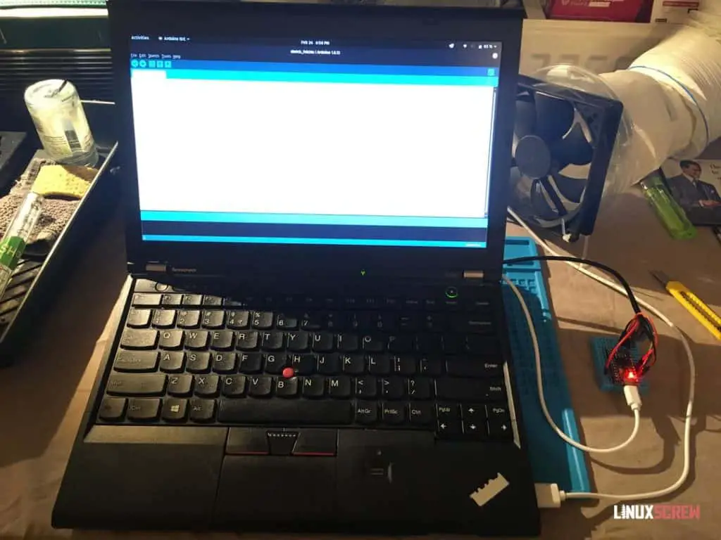
- Arduino IDE for Linux was used to write the code and load it onto the Arduino.
- Fritzing was used to make the circuit diagram shown below
All in all, there’s maybe 25 bucks worth of stuff here, so it makes for a good weekend project.
The Build
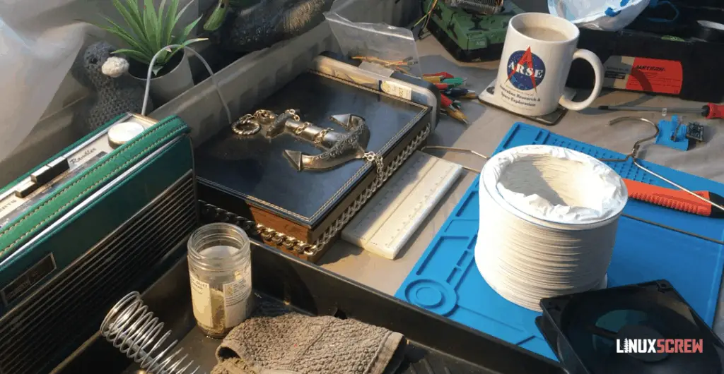
There’s not a lot to be said for the design of this – Various cylindrical scrap objects from my flat were tried in series until I found some that could be taped together to secure the fan to the plastic tube.
See the video at the end of the article for me fumbling about with various food packaging to get the job done.
Eventually, once everything fit, I secured it with tape to test.
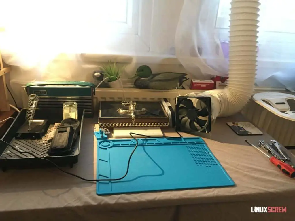
One of the first things I did was accidentally snap off one of the fan blades. It was later fixed with glue.
On testing – there was airflow at both ends! So that works. That nasty masking tape will be replaced later on with something less temporary.
The USB plug on the fan was lopped off and wired into the Arduino with button and sensor as follows:
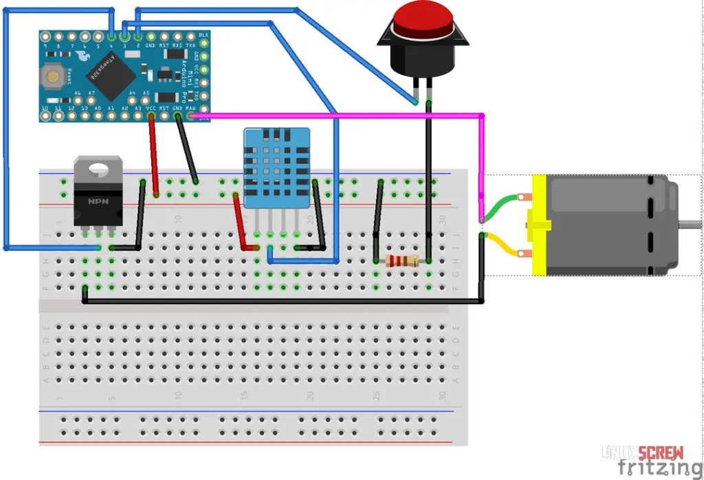
Fritzing is a great tool for visualizing your circuitry. Yeah, it’s not a real circuit diagram, but I haven’t made one of those since high school, and also, I don’t care – this illustrates what’s happening better anyway.
In the diagram above, you can see:
The fan is wired to the RAW power pin on the Arduino rather than VCC – the RAW pin isn’t present on all boards, but it’s a direct link to the board’s power feed.
If the fan is connected to VCC, which means it’s getting its power via the board and not directly from the PSU, it quickly causes issues as it draws too much current for the Arduino to handle.
The Code
I ran into a small issue using the Arduino IDE where I’d receive a ‘permission denied’ error whenever I tried to load my code to the Arduino device.
This is because Arduino IDE, when installed from some Linux app stores, is missing a dependency – simply run:
sudo apt install avrdude
… to resolve this.
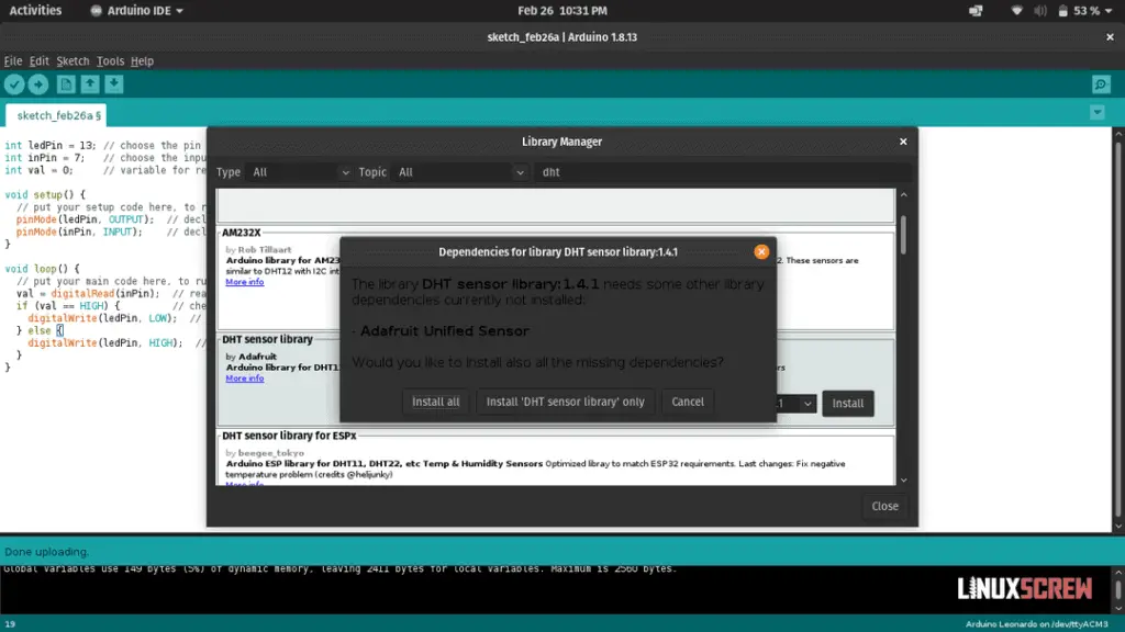
The upcoming code requires the DHT Sensor Library in Arduino IDE. It can be found by simply searching the available libraries and installing it from there. ‘Install All’ to install it with the required dependencies. See the video further down for carnage.
And without further fuss, here’s the Arduino code to run the automatic fan, with commentary:
// DHT sensor library can be found at https://github.com/adafruit/DHT-sensor-library
// It's available in the Arduino IDE libraries - just search for it

#include "DHT.h"

// Hardware configuration

int fanPin = 4; // Digital pin to control the fan via the MOSFET
long fanTime = 5000; // Number of milliseconds the fan will run for when triggered (5 Minutes)
int buttonPin = 2; // Digital pin the button is wired to
int dhtPin = 3; // Digital pin the DHT sensor is wired to
#define dhtType DHT11 // Define constant variable : Sensor type I have is DHT11, could also be DHT22 or DHT21

// Trigger conditions

int buttonState = HIGH; // The current button status - default unpressed (HIGH, as it's grounded on press!)
int triggerTemp = 25;// Temperature to trigger the fan at (Celsius)

// Initialize DHT sensor

DHT dht(dhtPin, dhtType);

// Setup function, runs once when the Arduino boots

void setup() {

  pinMode(fanPin, OUTPUT); // Set fan control pin as an output
  pinMode(buttonPin, INPUT); // Set button read pin as an input

  // Start outputting data on the Arduionos USB serial interface so that activity can be monitored from Arduino IDE

  Serial.begin(9600);
  Serial.println(F("DHT11 fan contoller ready."));

  // Start reading data from DHT module

  dht.begin();

  delay(3000); // Wait 3 seconds before continuing to the loop to give the hardware time to be ready

}

// Main code loop runs repeatedly while Arduino is powered

void loop() {

  buttonState = digitalRead(buttonPin);  // See if the button is currently pressed

  // Reading temperature/humidity from sensor takes about 250ms and values may be up to 2 seconds old as they are slow sensors

  float humidity = dht.readHumidity();
  float temperature = dht.readTemperature(); // Read temperature as Celsius - default
  float farenheit = dht.readTemperature(true); // isFahrenheit = true : Read temperature as Fahrenheit - not used in this script, but there for Yankees and... Burma?

  // Abort if any readings fail

  if (isnan(humidity) || isnan(temperature) || isnan(farenheit)) { // Read temperature as Fahrenheit - not used in this script, but there for Yankees and... Burma?

    Serial.println(F("Failed to take reading from DHT sensor."));
    return; // Exits, aborting this read attempt

  }

  // The DHT libarary can calculate the heat index if you want to use that as the trigger instead.

  float heatIndexFahrenheit = dht.computeHeatIndex(farenheit, humidity); // Heat index in Fahrenheit - default
  float heatIndexCelsius = dht.computeHeatIndex(temperature, humidity, false); // isFahreheit = false : Heat index in Celsius

  // Print out some data to the serial console so we know everything is working

  Serial.print(F(" Humidity: "));
  Serial.print(humidity);
  Serial.print(F("%  Temperature: "));
  Serial.print(temperature);
  Serial.print(F("C "));
  Serial.print(farenheit);
  Serial.print(F("F  Heat index: "));
  Serial.print(heatIndexCelsius);
  Serial.print(F("C "));
  Serial.print(heatIndexFahrenheit);
  Serial.println(F("F"));

  // Print the button state

  if (buttonState == LOW) {

    Serial.println(F("Button pressed."));

  } else {

    Serial.println(F("Button not pressed."));

  }

  // If the fan is triggered

  if (buttonState == LOW || temperature >= triggerTemp) {

    digitalWrite(fanPin, HIGH);  // Turn Fan ON
    Serial.println(F("Fan On!"));

    // Keep the fan on for the specified time
    delay(fanTime);

  }

  //When the delay after the fan is triggered is over, or the trigger condition hasn't been met, just make sure the fan is OFF

  digitalWrite(fanPin, LOW);  // turn Fan OFF
  Serial.println(F("Fan Off!"));

}
Temperature and humidity readings are output on the serial interface of the Arduino so that I can test things are working correctly.
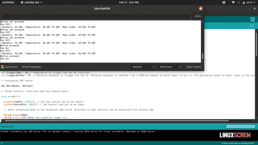
It Works!
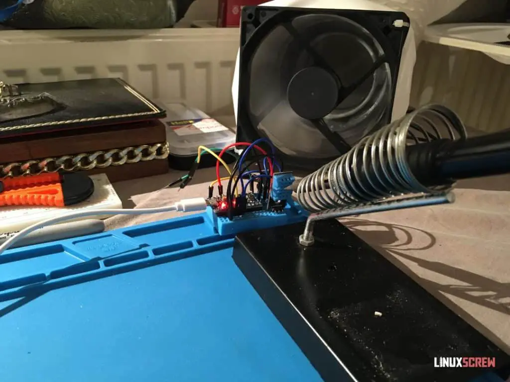
And just like that, it works. I really like the simplicity of making things on the Arduino platform.
When the soldering iron is on, it raises the temperature near the sensor, which then triggers the fan, which will turn off after 5 minutes after the temperature drops again.
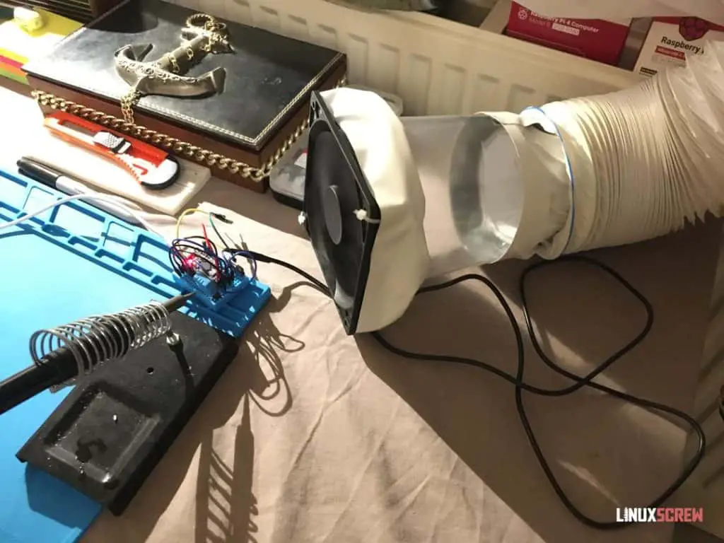
I also replaced the nasty masking tape from earlier with something a bit nicer. Looks good!
Improvements / Other Ideas
There are a few things I will probably do to improve this system:
- Investigate using an MQ135 gas sensor to trigger the fan when fumes are present instead of temperature
- Or, set it up so that it enables the fan when the temperature rapidly changes – it’s going to be hot in my flat in summer (the British apparently don’t believe in air conditioning) so having a simple temperature threshold probably won’t work
- A case!
- I could even mount it inside the soldering iron holster for convenience
Other Uses
The DHT11 sensor also handles humidity, so there are a few other things that could be done with a (tidied up) version of this:
- Automatic kitchen extraction fan, triggered by the heat of cooking
- Automatic bathroom extraction fan, triggered by the humidity of the shower running
- That’s about it, I guess
Video!
Seeing as I was setting up a new workspace, I decided to include a camera. I’m still getting used to positioning things, so they are in the shot, and there’s a lot of room for improvement, but let me know what you think!
If you want to see more of this stuff, follow LinuxScrew and myself on Twitter and let us know!


